|
Low-Voltage-Programming Cable
|

|

|
The LVP-Cable
(...dirty, but working;-)
|
|
This is a very simple in-circuit-serial-programming (ICSP) solution for PICs capable of low-voltage-programming (LVP). All you need are some resistors. You can integrate these few parts directly into a 9pin (or 25pin) SUB-D connector housing, or you could think about integrating them into your final device where your PIC will have to go to work (for doing software updates when necessary). For reading and writing program memory using this adapter, you also have to apply power to the PIC (+5V at Vdd) and tie MCLR to high level (Vdd) (Microchip suggests to use a resistor for MCLR because of latch-up risk). An oscillator circuit doesn't have to be connected. Of course, connect the three lines PGD, PGC and PGM to this adapter, too. |
 |
|
LVP-mode is enabled by high level on pin PGM. The second 10k resistor at PGM pulls this pin to ground if no PC is connected and thus safely prevents the PIC from entering LVP-mode. (If you either always stay connected to a PC or just use the adapter to programm the device, you won't need it.) |
|
|
Note that this circuit might not work on non-standard serial ports! Only voltage levels of +0V and +5V are sent back to PC instead of -10V and +10V. This works well on my desktop-PCs having a serial high-low threshold voltage of about +2V. But my notebook using an USB-serial-adapter didn't work with this circuit... |
|
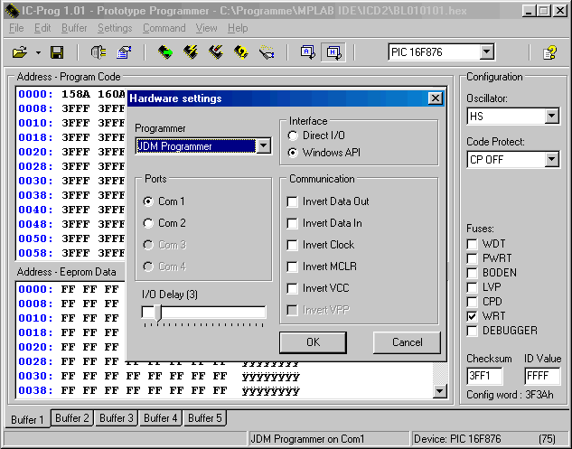
For programming, you can use ICProg from Bonny Gijzen. Configure as JDM-type-programmer (by reducing the setting of I/O-Delay you can speed up programming but increase the risk of errors).  The next picture shows a PIC16F870 ready for programming. The 10k against ground at Pin 3 of the Sub-D-Connector has been omitted (see above). For pulling up MCLR, a resistor connects PIC's Pin 1 to +5V.  Ok, I must admit, this method is not the finest way to get a PIC written but it's a very simply one. And well, finally that's what it's about here... |

|

|

|
|