WD5HOH Regenerative (REGEN) Radio Receiver


This web page describes a small, single tuned circuit regenerative receiver primarily for daylight reception in the 16, 19, 22 and 25 meter international shortwave broadcast bands. I have attempted to incorporate every improvement I have thought of into this receiver, including maximum mechanical rigidity and electrical shielding. This receiver is suited for reception of AM signals with the regenerative stage not oscillating. It's not an autodyne receiver. Oscillation is very noisy, but reception without oscillation is good.
I have borrowed a concept from bioinstrumentation: I treat a short wire antenna as an electrode rather than an antenna. The RF stage immediately following the antenna has an input impedance high enough so that the signal voltage on the antenna is essentially transferred to the gate of the first stage over the tuning range of the receiver without antenna tuning. I know from my reading that the maximum impedance the antenna will present to the receiver is about 2,000 Ohms. I placed a 2 megOhm bias resistor from gate to common at the input to a 2N3819 jfet and rely on that 2N3819 RF stage input impedance to be high enough compared to the antenna impedance that I can ignore antenna length over the tuning range of the receiver. The only way I can get away with that in the presence of the ever-present 60 Hz fields is to couple the antenna to the jfet gate with a small capacitance. And I can do that because the RF stage input impedance is very high. In this regenerative receiver I have installed ten capacitors ranging from three turns of hookup wire to 100 pF. I arrived at this configuration by experimenting in the field near a 60 Hz "drop" power line. This is very similar to the "active antenna" concept.
The receiver tuning technique I use which takes advantage of the switched antenna coupling capacitors is as follows: Let's say you have a weak station tuned in in the 19 meter(15 mHz) band, and the antenna coupling capacitance selected is 8pF. Let's further say that you have advanced the VERY FINE REGENERATION CONTROL as far clockwise as possible short of oscillation and that you have the signal tuned to the center of its carrier. You can then change the antenna coupling capacitance to 12 pF. You will notice an immediate drop in received signal level, but you can then advance the VERY FINE REGENERATION CONTROL further clockwise, and you will find you have somewhat greater signal strength than you did at 8pF. You will also notice that tuning with the FINE TUNING CONTROL is slightly broader than it was at 8 pF. You have slightly increased loading of the tuned circuit by the antenna(even though there is a jfet stage between the antenna and the regenerative stage). How far you carry this process depends on the proximity of powerful stations to the station you want to hear. It's a tradeoff between received signal strength and selectivity. It's a good choice to have available.
I wound bifilar coupling transformers with different numbers of turns, and settled on 75 turns as best. More turns can result in decreased tuning range. Fewer turns can result in decreased gain. The resonant frequency of this transformer was deliberately shifted down with a capacitor across the primary winding to give more or less uniform regeneration control over the tuning range of the receiver. There is a 1 megOhm resistor in parallel with the capacitor. This resistor makes the control of regeneration more nearly uniform over the receiver's tuning range. The inductance of the bifilar RF coupling transformer decreases the minimum frequency tuned by the receiver by at least 1.5 megaHertz.
I used a bifilar RF transformer to couple the output of the regenerative RF amplifier to the diode detector, and I connected the tickler coil to the bottom or cold end of the bifilar RF transformer primary to minimize the impedance change that the regenerative 2N3819 jfet drain sees when the regeneration control potentiometers across the tickler coil are adjusted. The mathematics to justify this circuit is as follows: The first derivative of the voltage gain with respect to the regeneration control resistance across the tickler coil is equal to the negative of the voltage gain squared divided by the total load resistance connected to the drain. See QEX, July/August, 2001, pages 53, 54. Also, it's important not to connect the bottom end of the bifilar RF transformer secondary winding to ground as would be necessary if a single detector diode were used rather than a bridge. Connecting the bottom end of the bifilar RF transformer secondary winding to ground greatly reduces receiver output. I know, I have tried it.
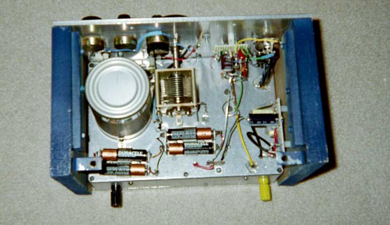
The tuning coil is wound with approximately AWG 18 enameled magnet wire on a cross-linked polyethylene (PEX) cylindrical form. Each end of the winding is passed through two holes drilled in the form with approximately ½ inch of protruding magnet wire scraped clean of insulation. These two bare copper ends serve as terminals for the coil. The coil is mounted on the chassis deck with small angle brackets, machine screws and nuts. The tuning coil, mounted above the chassis is shielded by an empty steel food can. Stability of this receiver's tuned circuit is enhanced by very slightly compression loading the coil form by making it very slightly longer than the shield can. The angle brackets on the shield can are located just above the raised "lip" on the lower edge of the(empty soup) can so that tightening these screws compression loads the coil form. Spacing between the coil, chassis deck and shield can follows the guidelines in the 1992 ARRL handbook for shielded inductors.
I have made an effort to lay this receiver out for the most direct possible point-to-point wiring. There is a SPST toggle switch which connects a 33 pF capacitor across the tuned circuit to allow 25 meter band reception. The connections from the 140 pF tuning capacitor and the tuning coil to the RF circuit board below the chassis deck are made with AWG number 14 solid insulated wire. Hot glue was used as a "grommet" where this wire passes through holes in the chassis deck. The same technique was used where RG 178/U coaxial cable and solid hookup wire passes through holes in metal.
The receiver was built on a diecast aluminum chassis with a rubber “foot” at each corner. The chassis wall thickness is 0.075 inch. The RF circuit board is held above the inside bottom surface of the chassis with machine screws and nylon spacers. Main or coarse tuning is accomplished with a high quality 140 pF anodized variable capacitor bought on Ebay driven by an Argonne AR-404 Vernier drive also bought on ebay. Fine tuning is done with a “floating rotor” variable capacitor driven by a small Vernier drive. The floating rotor tuning capacitor has two fixed aluminum plates separated by an air gap. An aluminum rotor held and driven by a small Vernier drive moves in and out between these fixed plates varying the capacitance as it moves. The overall capacitance change from "rotor in" to "rotor out" is on the order of 0.1 pF, but this capacitance change is more than enough to tune completely through a received signal. The floating rotor capacitor is very good for tuning precisely to the center of a received AM signal. Its location close to the very fine regeneration control makes it easy to tune and optimize a weak signal. The receiver front panel is 1/8 inch thick aluminum which qualifies as "plate" rather than "sheet". The thickness of the front panel complicates construction because not all potentiometers have long enough threaded bushings for such a thick panel. Also, the die cast chassis has sloping sides which make it necessary to mount some components to the front panel rather than the chassis. Most of the radio frequency circuitry is under the chassis deck. There are two 3/4 inch thick wooden "end pieces" bolted to the diecast chassis. These serve to damp any vibration of the chassis and front panel. The audio amplifier/driver is located under the chassis deck and is isolated from the RF circuits by an aluminum shield partition. This partition has through holes for interconnecting wires and cables to pass. There is a jfet source follower immediately following the 1N34 bridge detector. This circuit uses a miniature audio transformer to provide some voltage gain.
Regeneration control is improved by running a length of RG-174/U coax from the circuit board to the regeneration control potentiometers wired so that the coax shield carries the supply voltage. The supply voltage is at or near RF ground. Small considerations like this do make a difference. I have tried it both ways.
This receiver is powered by four 1.5 Volt AA cells in series in aluminum battery holders. Regulation has been found to be unnecessary. The operating point of the antenna matching stage was recalculated from previous 9 Volt designs.
“Fringe howl” serves as a good fine tuning indicator: As the “very fine” regeneration control is backed down from outright oscillation to fringe howl the fringe howl can be tuned to “zero beat”. That means you have tuned in an AM signal exactly in the center of the carrier at maximum RF gain. You can then increase audio gain. And this tuning can be accomplished at the highest frequency this receiver tunes. If your receiver is built well enough you should be able to tune it as just described to a signal of moderate strength near 17 mHz, “bump” the receiver with your hand and observe very little difference in receiver output and no "microphonics". Isolation of all audio circuits is essential for effective operation of this receiver just below oscillation. I verified the validity of this approach by temporarily mounting the audio follower circuit board incorporating an audio transformer close to the main RF board with a less than rigid mounting. The increase in microphonics was immediate and unmistakeable, and overall receiver performance was degraded. This circuit board was then mounted above the chassis deck against one of the wooden end pieces of the receiver enclosure with a resulting substantial improvement in receiver performance. The microphonics were gone.
The "gimmick" coupling capacitor between the first and second stages consists of two lengths of AWG #22 hookup wire twisted together. Each piece of wire was stripped of insulation at one end and soldered to the appropriate RF circuit board wiring at one end. The pieces of wire were then twisted together for about 6 turns so that the completed coupling capacitor was mounted to the board perpendicular to the board. When the receiver was complete and operational this coupling capacitor was trimmed one or two turns at a time until receiver performance was correct.
Be advised that 2N3819's from different manufacturers behave differently. This receiver was first assembled with Vishay-Siliconix 2N3819's. Nothing I could do would make the receiver oscillate over the entire tuning range. I then completely stripped the RF board and rewired it from scratch using a Fairchild 2N3819 for the regenerative stage and an old Motorola 2N3819 for the input stage(the Motorola 2N3819 having worked well in an earlier similar receiver at that position). It then worked as intended and continues to work very well. The audio section has two Vishay-Siliconix 2N3819's and works well.
KEEP ONE THING IN MIND: IF THE COMPLETED RECEIVER DOES NOT REGENERATE REVERSE THE WIRES CONNECTED TO THE TICKLER COIL.
Smoothness of operation of the main tuning Vernier drive requires some persistence. I have mounted the main tuning capacitor with a nylon screw to its rear mounting lug only and have carefully adjusted the height of the rear mounting lug of the capacitor for minimum "drag" on the main tuning knob. The nylon screw has some flexibility and allows the capacitor to move slighty to compensate for misalignment. It was also necessary to partially disassemble the main tuning Vernier drive and tighten four small screws just under the dial plate(the head of one of then was visible at an odd angle behind the dial plate, and all of them turned out to be loose). I made an improvised holder for the small dial plate hold-down screws from a thin, stiff strip of cardboard with a hole near one end for the screws and a cut at the end to allow the screw holder to be removed from the partially tightened screw by pulling. Putting them in with your fingers doesn't work.
Initial operation of this receiver has been encouraging. I tried listening on 19 meters at about 0400 UTC(11:00 pm here) and was surprised to hear Radio Norway with a good signal, and Radio New Zealand has been heard with fair signal strength in South Texas, USA. I use a sloping wire antenna about 35 feet long, maximum height about 25 feet.
Precise frequency measurement of received signals is possible with this receiver because I have a home brew diode stabilized VFO with digital readout that sits near the operating position. The VFO can be switched on and adjusted for zero-beat with the received signal. First,second, third and even fourth harmonics are received clearly. I always seem to be able to read received frequency to the nearest 200 Hz which is close enough.
Control of regeneration of this receiver is best done as follows: Turn the COARSE regeneration control fully CCW. Turn the FINE and VERY FINE regeneration controls fully CW. Choose the appropriate antenna coupling capacitor for the band being tuned, and set the FINE TUNING CAPACITOR to about mid-range. With receiver power on and the AUDIO GAIN set to about 3/4 fully CW carefully turn the COARSE regeneration control CW until a rather harsh continuous noise is heard. You want to be no further CW than is necessary to sustain this noise. Then turn the FINE regeneration control CCW until the noise just stops, then enough CW to sustain the noise. Do the same thing with the VERY FINE regeneration control. You should now be able to tune with the tuning controls and control regeneration with the VERY FINE regeneration control.
BILL YOUNG WD5HOH
Article originally at http://www.hal-pc.org/~blyoung/